
A to Z of Class-A 3D Modeling: The Definitive Guide to Production Surfacing
2026-07-27
Welcome to the deep end. If you're here, you're not just curious about 3D modeling—you want to know what separates a show-stopping car design from a kit car that looks "a bit off" in certain lighting. You're here to learn about Class-A surfacing.
Class-A surfacing is the discipline of creating mathematically perfect, aesthetically flawless, and manufacturing-ready digital surfaces. It is the language of automotive design and high-end industrial design. If a surface isn't Class-A, it doesn't belong on the exterior of a production vehicle or a high-quality aftermarket body kit.
This guide is your A-to-Z. It's written for aspiring designers, CAD surfacers, and shop owners who want to move beyond mesh-based 3D printing and understand the real standards of the automotive industry.
Why Class-A Surfacing Exists
The difference between Class-A and everything else is physics. A mesh model from Blender or a ZBrush sculpt looks fantastic on a screen because the render engine fakes the lighting.
But light doesn't care about your renders. When a physical panel is painted, the clear coat acts as a mirror. The human eye is an incredibly sensitive instrument for detecting reflection distortion. If your surface isn't smooth at a mathematical level, the reflections will "wobble" or "kink." A Class-A surface guarantees that the light flows over the panel like water, highlighting the design's muscle and form.
This isn't vanity. In the real world, a hood-to-fender transition that isn't Class-A will result in a visible "crease" or distortion under paint. That means rejected parts, scrapped tooling, and thousands of dollars in wasted time. For OEMs, Class-A is non-negotiable. For smaller shops aiming for professional results, it's what builds a reputation.
Core Technical Principles
To master Class-A, you must understand the physics of the curve.
Surface Continuity: G0, G1, G2, and G3
Continuity defines how two surfaces connect.
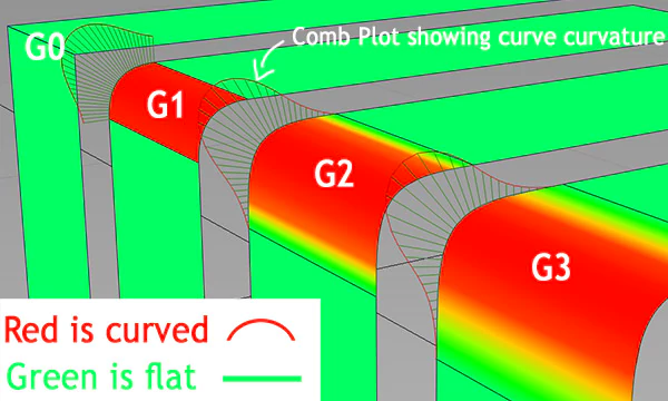
- G0 (Positional Continuity): The surfaces meet at a seam. There is no gap, but there is a sharp edge.
- G1 (Tangent Continuity): The surfaces meet and share a direction. You get a smooth corner, but it isn't necessarily a "smooth" transition.
- G2 (Curvature Continuity): This is the standard for Class-A exteriors. The surfaces meet, share a tangent, and the rate of curvature is the same on both sides. The highlight reflections flow smoothly across the seam.
- G3 (Acceleration Continuity): This is used for ultra-high-end design or specific fish-tail transitions.
Analyzing the Surface
To achieve G2, you can't just "eye-ball" it. You need analytic tools.
- Zebra Stripes: These simulate reflection lines. If the stripes are broken or kink, you have a continuity issue. If they flow smoothly, your surface is likely good.
- Curvature Combs (Porcupine): These display the radius of curvature along a surface or curve. In a Class-A surface, the comb should flow smoothly, without sudden spikes.
- Single-Span vs. Multi-Span: NURBS surfaces are built with "spans." A single-span surface is the purest mathematical form and yields the best reflections. Multi-span surfaces can be harder to control. Class-A favors fewer, cleaner spans to maintain control over reflection behavior.
Control Points and Degrees
Control Points (CVs) are the "handles" that pull the surface into shape. A common beginner mistake is adding too many control points. More points give you more local control, but they also introduce "waviness."
Class-A modeling is about using the fewest control points necessary to achieve the design intent. This is known as the "degree" of the surface. A cubic surface (degree 3) is standard, while degree 5 is used for more complex curves.
NURBS vs. Polygon/Subdivision Modeling
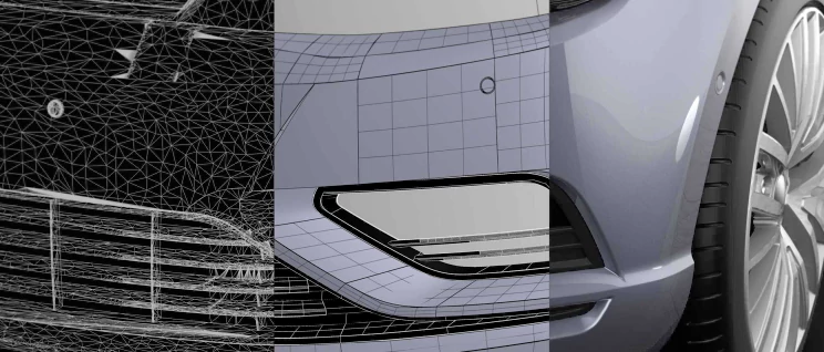
The industry standard for Class-A is NURBS (Non-Uniform Rational B-Splines).
Why NURBS Wins
- Mathematical Precision: NURBS uses equations to define the surface. This makes it possible to manufacture parts with a tolerance of 0.1mm or better.
- Continuity Control: You can explicitly set G1, G2, or G3 continuity between patches.
- Manufacturing Data: NURBS exports cleanly to CNC machinery and tooling molds.
Where Polygons Fit
Polygon modeling (in Blender or ZBrush) is perfect for the design phase. Styling clay models and concept sculpting are often done in subdivision surfaces because they are fast and intuitive.
The common workflow is:
- Polygons: For ideation and concept.
- NURBS: For the final production surfaces.
- Polygons: For rendering or visualization.
The Real Production Workflow
Here’s how it actually happens, from napkin to production.
Phase 1: Concept and Data
The process begins with a sketch or a 3D scan. To start modeling, you need a "reference." This could be a physical clay model, a scan of a competitor's design, or a simple sketch. You align your NURBS software (like Alias) to this reference.
Phase 2: Primary Surfacing
This is where the magic happens. You lay down the "keylines." For a front fender, this means the character line that runs from the headlamp, the wheel arch, and the seam to the hood. The primary surfaces define the architecture of the car.
Phase 3: Continuity Checking
Once the primary surfaces are built, you check continuity. If the fender meets the hood with only G1, you'll see a "crease" in the zebra stripes. You must patch the surfaces to achieve G2, often using fillets or blends.
Phase 4: Validation and Handoff
This is the most critical step. You validate the model against "physical constraints." Are the tolerances tight enough? The final deliverable is usually a STEP or IGS file—the universal languages of manufacturing.
Phase 5: Manufacturing
The STEP file goes to a tool and die maker. For carbon-fiber or fiberglass, the file is used to create the mold. CNC machines use it to cut the tooling.
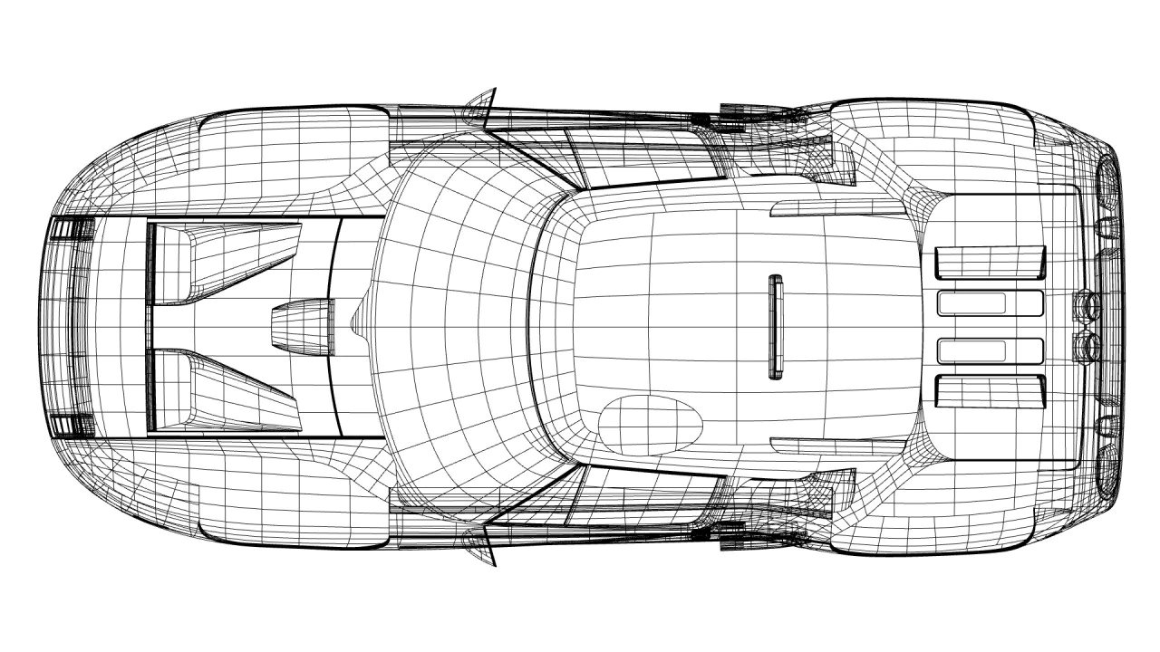
Common Mistakes Beginners Make
- Chasing the Render: Don't make decisions based on the high-gloss render. Make decisions based on the curvature combs and zebra stripes. If the analysis is clean, the render will be beautiful.
- Over-Surfacing: Too many patches mean too many seams. Class-A models aim for the fewest patches possible.
- Ignoring the "Shadow": Beginners often forget to check the surfaces in "black" or a dark environment. A surface that looks perfect in the sun might look muddy in the shadows.
- Ignoring Physical Constraints: You can model a beautiful 500mm fender flare, but can you pull it from the mold? Does it fit within the vehicle's envelope?
Tools of the Trade
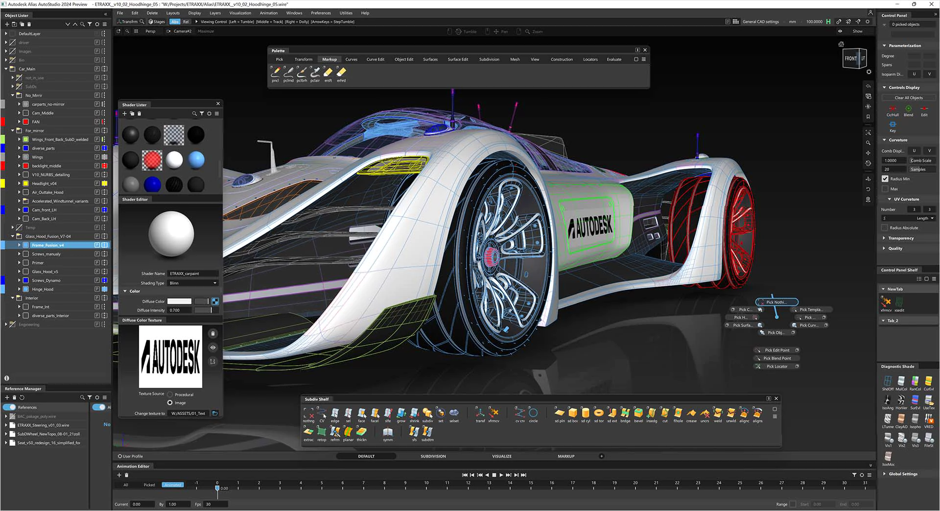
- Autodesk Alias AutoStudio: The gold standard for Class-A. It is the Ferrari of 3D modeling.
- ICEM Surf: The competitor to Alias. Very powerful and used widely in the aerospace and automotive industries.
- Catia (ICEM/GSD): For engineering-led surfacing. Often used for the final "Class-B" or structural surfaces.
- Autodesk VRED: Used for high-end visualization and "reality checks" before a physical prototype is built.
- 3D Scanning: Essential for reverse engineering. You can scan a clay model, plug the data into Alias, and build a production-ready Class-A surface from it.
How This Applies Beyond OEM
Class-A surfacing isn't just for million-dollar supercars. The aftermarket industry (body kits, tuners, and carbon-fiber shops) relies on it to stand out.
If you are building a widebody kit for a Porsche or a BMW, the fitment must be perfect. A gap that is 1mm out of tolerance will be visible. A surface with poor continuity will look like an ebay special under paint.
By learning Class-A, you elevate your work from "kit" to "engineering." You become the person who can take a 3D scan of a car and reverse-engineer the fender lines to create a bolt-on part that looks OEM.
How to Start Learning Class-A Surfacing
- Step 1: Fundamentals: Learn the mathematical theory. "The NURBS Book" is heavy reading, but it provides the foundation. You must understand "degree," "span," and "knots."
- Step 2: Software: Download Alias SpeedForm or a free trial of ICEM.
- Step 3: Practice: Start with simple shapes—a perfect teardrop, a shoebox, a knurled grip. Understand how to achieve G2 on a cylinder.
- Step 4: Complex Models: Move on to a quarter panel or a bumper. Try scanning a model and rebuilding it. This is the best way to learn.
- Step 5: Community: Alias has a steep learning curve. Find a forum, take a course, and critique other people's work.

FAQ
What is Class-A surfacing in 3D modeling?
Class-A surfacing refers to a set of mathematical and aesthetic standards for 3D surfaces. It ensures the surface is free of "waviness," has specific continuity (G1/G2), and is manufacturable. It is used primarily for exterior vehicle body panels and high-end industrial design.
Is there a difference between Class A and Class B surfacing?
Yes. Class-A surfaces are aesthetic and reflection-critical (e.g., hoods, fenders). They require high continuity and a flawless look under paint. Class-B surfaces are invisible to the user (e.g., engine brackets, inner panels) and only require G0/G1 continuity for fitment and function.
Why is NURBS used for Class-A surfaces?
NURBS are used because they offer mathematical precision. Unlike polygon meshes, NURBS surfaces are defined by equations, allowing for exact control over curvature and tangency. This precision is mandatory for tooling and high-quality manufacturing.
Can I use Blender for automotive Class-A surfacing?
Technically, yes, but it's not standard. Blender lacks the advanced continuity analysis tools and specific manufacturing workflows found in Alias or ICEM. For professional work, Alias AutoStudio is the industry standard.
What is the difference between G0, G1, and G2 continuity?
- G0: The edges touch (positional).
- G1: The edges touch and are tangent (direction).
- G2: The edges touch, are tangent, and have matching curvature (rate of change). G2 is the minimum for Class-A exterior work.
How much does Class-A surfacing software cost?
Professional suites like Autodesk Alias can cost thousands per year. However, educational versions or limited tools like Alias SpeedForm are more affordable or free for students and enthusiasts, providing an excellent entry point.
Conclusion
Class-A surfacing is the intersection of art and physics. It is difficult to learn, but it is the only path to professional-grade automotive design. If you master the NURBS tools, the continuity theory, and the manufacturing constraints, you can produce work that competes with the best in the world.
I've built a career on this. From OEM programs to high-end aftermarket body kits, the principles are the same. If you want to take your design work to the next level, this is where you start.
If you want to see what this looks like in practice, check out my portfolio. If you have a project that needs to look like it belongs on a showroom floor, let's talk.